Wednesday, May 25, 2011

Diff 4844 kavit jay

Differential with hypoid gears

In practical class we dismantled a differential and inspected the condition of each component in the diff housing.

We first marked the diff housing caps and marked the crown wheel position this is so that when the diff is reassembled when we can correctly align the housing and crown wheel.

We then removed the diff case assembly, unlock & removed all the crown wheel bolts and removed the crown wheel with all components in the diff housing.

Driven gear assembly inspection

Condition of crown wheel teeth

The condition of the crown wheel teeth is good; there were no pits around the teeth. This can be caused small bumps on the teeth of then pinion gear when the teeth contact.

The teeth of the crown wheel were smooth and no indentations were found that can be caused by a large load on the contact between final drive gears.


The crown wheel is driven by the pinion gear which drives the side gears.
The crown wheel supplies the power to side gears in the diff housing and finally transmitted out to the wheels


Condition of the crown wheel bolts

The crown wheel bolts had some rounding on the top caused by wrong socket or spanner size, overall the threads were in good and not cross threading were found.

The crown wheel bolts hold the crown wheel on to the diff housing with a total of 10 bolts


 Removing and condition of the cross shaft

Removing the roll pin we first had to tap out the cross shaft, the taping the pin with a brass punch. The roll pin had some small scratch marks around the shaft maybe caused by removing of the shaft but are not serious.


The cross shaft sits in between the side gears to hold the gear assembly in place with a pinion shaft to lock it in place, there are flat surfaces on the shaft which allow for lubrication.


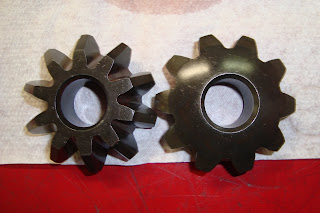
Spider gears

Removing the spider very easy by rolling the side gears around until the spider gear fall out by their own. We found no thrust washers on any of the gears in the diff case.

Some of the spider gears had small marks on the face of each teeth, this is because of the pinion gear is to far forward to correct the alignment we would have to place some shims on bring the  pinion gear back for proper teeth contact.


The spider gears walk around the side gears when the vehicle is turning, the spider gears allow for the inner wheel to rotate slower than the outer wheel when turning. When the vehicle is driving on a straight road the spider gears do not walk around the side gears and only turn with side gears


Side gears


The side gears hade some rust on the teeth which can cause pitting and will eventually have to be replaced. The side gears also have small indentation on each tooth which looks like line after line groves it could be manufactured like this for a purpose.


Pinion gear

The pinion gear was very smooth when we removed it from the case some of the tooth had small chips on the tips which was most likely caused by incorrect tooth contact

The purpose of the pinion gear is to drive the crown wheel; the pinion gear is connected to the drive shaft, also the pinion gear is positioned at the center of the crown wheel with hypoid gear tooth


Diff case
Inside the diff case there was no thrust washer which goes behind the spider gears causing pitting and small rust.


The purpose of the differential housing is to house the side and the spider gears 


Wednesday, May 18, 2011

4844 Engine and drive kavit jay.

Universal cross joints

The universal cross joint allows the power from the gear box to be transferred to the output drive shaft at and angel of up to 12 degrease any more than 12 the drive shaft will start to vibrate.
  

Visual check

We first carried out a visual check of the cross joint and found rust developing on the cross joint cups and yoke but were not major. There was quite a lot of dirt build up around the yoke.

Removing clips


Removing the clips were difficult because of the dirt that hardened up around them, however the four clips must be removed so the cross cups could be taped out.
Removing cups


We then clamped the yoke to the vice making sure the vice is not clamping the drive shaft that could damage the shaft, making the shaft unbalanced. It was difficult to tap the cups out of the inner yoke because of some minor rust between the yoke and cups sides. We removed any grease on the cross joint and yoke so we could properly inspect for wear. We inspected the universal joint surfaces, rollers and the yoke surfaces, all are in good condition.

Lubricating

We then greased the cross joint and yoke to lubricate the metal surfaces for future wearing and reassembled the universal cross joint in reverse.

Wednesday, May 11, 2011

4841 electrical Resistors

Resistors

Today we went covered resisters; they are mainly used of creating a resistance in a circuit when some components cannot handle the current of the supply voltage

readings

Band colours
Measured value
Low tolerance
High tolerance
Pass/fail
Red red
22 +-5%
21.8
20.7
22.9
pass
Ble gry yelw
684000+-5%
695000
660000
729000
pass
Org org bwn
330 +-5%
327
310
343
pass
Bwn rd
82 +-5%
81.1
77.0
85.1
pass
Grn blu bwn
560 +-5%
551
523
578
pass

Resistor1. 21.8ohms / resistor2. 695ohms

1 and 2 in series 699ohms

In series the resistance increases with each resistor added to the circuit so total resistance is all the resistors added up.

1 and 2 in parallel 21.8ohms

In parallel the total resistance should be lower than the smallest resistor, the more resistor you put in a circuit the less resistance becomes.

4841 electrical Relays

Relays

This week in class we coved basic relays relays van be used for switching between dips to high beam on the headlight circuit.

We used a 5 pin relay 86 and 85 are the control side of the relay and 30, 87, 87a is used for switching which carry higher amps.
readings

Circuit off
Circuit on
86                        13v 
86                         13v
85                        13v
85                           0v
30                        13v
30                         13v
87a                      13v
87                           0v 
87                         0v 
87a                        13v

86. There was available voltage on the point 86 because it is the input.

85. There was a 13v volt drop on 85 because the voltage was consumed when the           switch was closed

30. There is a 13v available voltage because it is again the input positive.

 87a.There is 13v in 87a because the circuit is off and the magnetic coil is not magnetized to pull the switch to 87. This could be the dip lights engaged.

87. Now 87 is 0v because the circuit is on and the magnetic coil is magnetized and it pulled the switch to 87 to complete the circuit. This could be now switched to high beam 

Thursday, May 5, 2011

starter motors 4841 electrical

Stater motors

Pull in and hold in windings

This week in class we went through starter motors, we leant that when the ignition key is turned electricity from the battery triggers the starter motor solenoid that engages the pull in windings. When the pull in windings are engaged it completes a circuit on the contacts which activates the hold in winding, the plunger shifts back and moves the shift lever towards the clutch. The pinion drive gear then slide into the ring gear teeth on the flywheel, the pinion drive gear then rotates and turns the flywheel until the engine is started. When the ignition is turned off the circuit is then broken and the hold in winding are no more and the pinion drive gear is moves back in a helix rotation.


 Bench test

We first had to test the starter motor on the bench test and get a volt and amperage readings we got 11.9v and 33.8 amps which meets the specs.

Visual inspection

We then carried out visual check on the armature and field coils, pole shoes we checked for overheating, burning, physical damage and poling we found none of these in the inspection.
Readings

We got reading for the ground test from the commutator segments and the armature core shaft 1k or infinity which means that there is low resistance so more amps can flow through.
Armature continuity test

Armature continuity test gave us a reading of 0.01 ohms again good for conduction.
Commutator diameter

When we measured the diameter of the commutator we got 32mm which is above the specs of 26.8 – 31 we aren’t Shure why but could be because of overheating.

Brush readings

All our 3 brush readings were 5mm and were not worn or damaged and are in good condition.

solenoid magnetic switch

We tested the pull in winding on the solenoid by connecting negative on the M and back out the pull in windings were functioning correctly. We obtained a 10amp reading which meets the specs.
hold in test

In the hold in windings we had to connect the positive to the S terminal and earth the negative to the body of the solenoid, in result the solenoid plunger pulled in and held in we also got a reading of 8 amps which meets the specs.

Putting the alternator together

When we assembled the alternator together we accidently pulled out wirings on the brush connections. We had to solder the wire back together and assemble it. When we carried out a bench test there was an increase in voltage and amperage from the last test 33.8amps to 45.1 amps and 11.9v to 12.26v this could be a result of the soldering we did

Wednesday, May 4, 2011

4841 electrical battery. kavit jay


This week in class we went through the function of the battery.The battery supplies voltage to the starter motor to turn over the engine, and also provides voltage to the electronic components which maintain the electrics in the vehicle while being driven


Inside the battery there are 6 positive and negative cell plates and in between separating the two plates are called ribs so there is no contact between them.


Inside the battery there is an acid called sulfuric acid h2so4 this acid is highly dangerous and can burn through cloths and skin always wear eye protection and overalls.


04/05/2011
            
 In practical class we carried out a battery service test

Visual check

We first checked for any loose connections and corrosion around the battery which could result in high resistance.

Electrolyte levels

We then moved on to checking the electrolyte levels in each cell, all the cells had a reading around 1.200 to 1.275 which was in the green colour level indicating (GOOD).

OCV voltage

We then carried out an OCV test using a multimeter set on 20v and obtained a reading of 13.9v this reading means that there was surface charge on the engine which needed to be removed by sustaining a load on the battery; this is done by cranking the engine or leaving the fan running for a minute.
The reading we then got was 12.8v which is a fully charged battery 100%.

Checking colour and gavity variation

cell
1
2
3
4
5
6
reading
1.275
1.250
1.225
1.250
1.225
1.200
colour
clear
clear
clear
clear
clear
clear

These are the readings we received after the test as above, this shows that there was some different electrolyte levels and needed to be filled with battery water to a level of 1.275 roundabouts. Our gravity variation is 75 and the specs are 25-50, which is above the specs

Load test

we then moved on to a load test we fist connect the volt meter to the battery to receive reading under the load, then we connected the load tester to the battery and cranked the amps to half of the batteries CCA which was 300 so we set it to 150amps for 10 seconds.

We got a reading of 10.4v under 150amp load on the battery which meets the specs of above 9.5v that an ordinary battery should hold.